


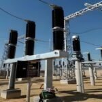
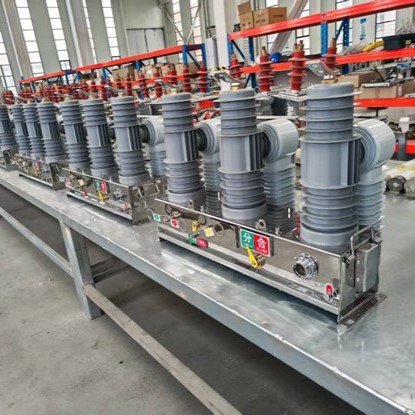
GW5-40.5/126 Outdoor High-Voltage Disconnect Switch
The GW5-40.5/126 Outdoor High-Voltage Disconnect Switch is a newly developed model based on our previous series, designed to fully meet the enhanced technical requirements issued by the State Grid Corporation.
This upgraded design focuses on addressing key performance aspects such as heating of the conductive circuit, improved conductivity and reliability, elimination of mechanical jamming, anti-corrosion of bearing seats, enhanced surface protection, and simplified on-site installation.
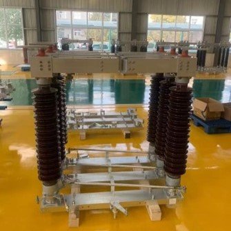
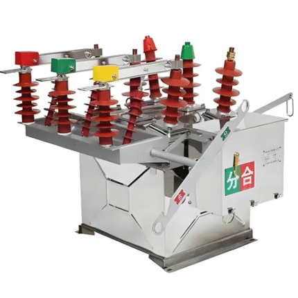
The switch consists of three independent poles, each featuring a V-shaped double-column structure, and is composed of a base, insulator posts, and conductive components. Each pole includes two insulator columns installed at a 50° angle, mounted on bearing seats connected to the base. Opening and closing operations are driven by a four-link transmission mechanism.
The conductive blades include left and right contacts, each fixed on the insulator columns. Depending on installation needs, the product is available in multiple configurations: standard upright installation, side installation, and side installation options at 25°, 50°, or 90°.
Product Features
♦ External-pressure contact finger design
The contacts are hard silver-plated for improved conductivity and durability. The conductive rod is made of square aluminum tubing, increasing heat dissipation area and enhancing conductive reliability, with a tin-plated surface for added protection.
♦ High-reliability flexible connections
Flexible connectors are fixed between terminal seats to ensure stable current flow. The terminals use insulated bushings on both ends to maintain conductivity and smooth rotation. The terminals and output posts are integrated into a one-piece structure, eliminating a potential hot spot.
♦ Fully sealed bearing seat
The bearing base adopts a fully sealed, dual-layer upper and lower sealing structure, preventing rainwater and dust intrusion. Bearings are filled with wide-temperature lubricant (–40°C to +120°C), ensuring consistent performance in both extremely cold and hot climates.
♦ Corrosion-resistant transmission system
All transmission pins are made of stainless steel. German-imported igus® engineering plastic bearings replace traditional brass bushings to prevent seizure and corrosion. Stainless-steel rod-end bearings are used at transmission joints, ensuring long-term smooth, lightweight operation.
| No. | Item | Unit | Technical Parameters | |||||
|---|---|---|---|---|---|---|---|---|
| 1 | Rated Voltage | kV | 40.5 | 126 | ||||
| 2 | Rated Frequency | Hz | 50 | |||||
| 3 | Rated Current | A | 1250 | 2000 | 2500 | 4000 | ||
| 4 | Main Circuit Resistance | μΩ | ≤200 | ≤150 | ≤100 | ≤85 | ||
| 5 | Temperature Rise | Test Current | A | 1.1 times Rated Current | ||||
| 6 | Rated Power-Frequency 1 min Withstand Voltage | To Ground | kV | 95 | 230 | |||
| Across Break | 118 | 230+70 | ||||||
| Rated Lightning Impulse Withstand Voltage (1.2/50ms) Peak | To Ground | kV | 185 | 550 | ||||
| Across Break | 215 | 550+100 | ||||||
| 7 | Rated Short-Time Withstand Current and Duration | Disconnecting Switch | kA/s | 25/4 | 31.5/4 | 40/4 | 40/4 | |
| Earthing Switch | 25/4 | 31.5/4 | 40/4 | 40/4 | ||||
| 8 | Rated Peak Withstand Current | kA | 63 | 80 | 100 | 100 | ||
| 9 | Bus Transfer Current Switching Capability | Transfer Current | A | 1600 | ||||
| Transfer Voltage | V | 100 | ||||||
| Number of Breaking Operations | Times | C-O 100 times | ||||||
| 10 | Switching of Small Capacitive Current | A | 1 | |||||
| 11 | Switching of Small Inductive Current | A | 0.5 | |||||
| 12 | Earthing Switch Switching of Induced Current Capability | Electromagnetic Induction | Inductive Current | A | 50 | |||
| Recovery Voltage | kV | 0.5 | ||||||
| Number of Breaking Operations | Times | O, C 10 times each | ||||||
| Electrostatic Induction | Capacitive Current | A | 0.4 | |||||
| Recovery Voltage | kV | 3 | ||||||
| Number of Breaking Operations | Times | O, C 10 times each | ||||||
| 13 | Mechanical Stability (Durability) | Times | 3000 | |||||
| 14 | Short-Time Power-Frequency Withstand Voltage for Auxiliary and Control Circuits | kV | 2 | |||||
| 15 | Static Mechanical Load on Terminals | Horizontal (Longitudinal) | N | 800 | 1000, 1250 | |||
| Horizontal (Transverse) | 500 | 750 | ||||||
| Vertical | 750 | 1000 | ||||||
| 16 | Post Insulators | Creepage Distance | mm | ≥1256 | ≥3906 | |||
| Post Height | 550 | 1200 | ||||||


Reviews
There are no reviews yet.